Agenda
- CDR Objectives & Scope
- M1 Design Overview
- Support System Architecture
- Optimization & Cost Reduction Campaign
- Selected Design — Option B Performance
- Recent Development: Refined Contact Model
- Boundary Condition Strategy
- Reference Frame — Scope & Requirements
- Risk Assessment
- Path Forward & Recommendation
CDR Objectives
Goal: Establish design maturity sufficient to authorize blank procurement from Schott.
- Validate M1 design meets optical & mechanical requirements
- Document cost reduction campaign & trade-off analysis
- Present final design selection with supporting data
- Define support system architecture & reference frame concept
- Establish procurement path & timeline
Scope: M1 blank design + support system architecture.
Reference frame detailed design & STOP analysis → FDR phase.
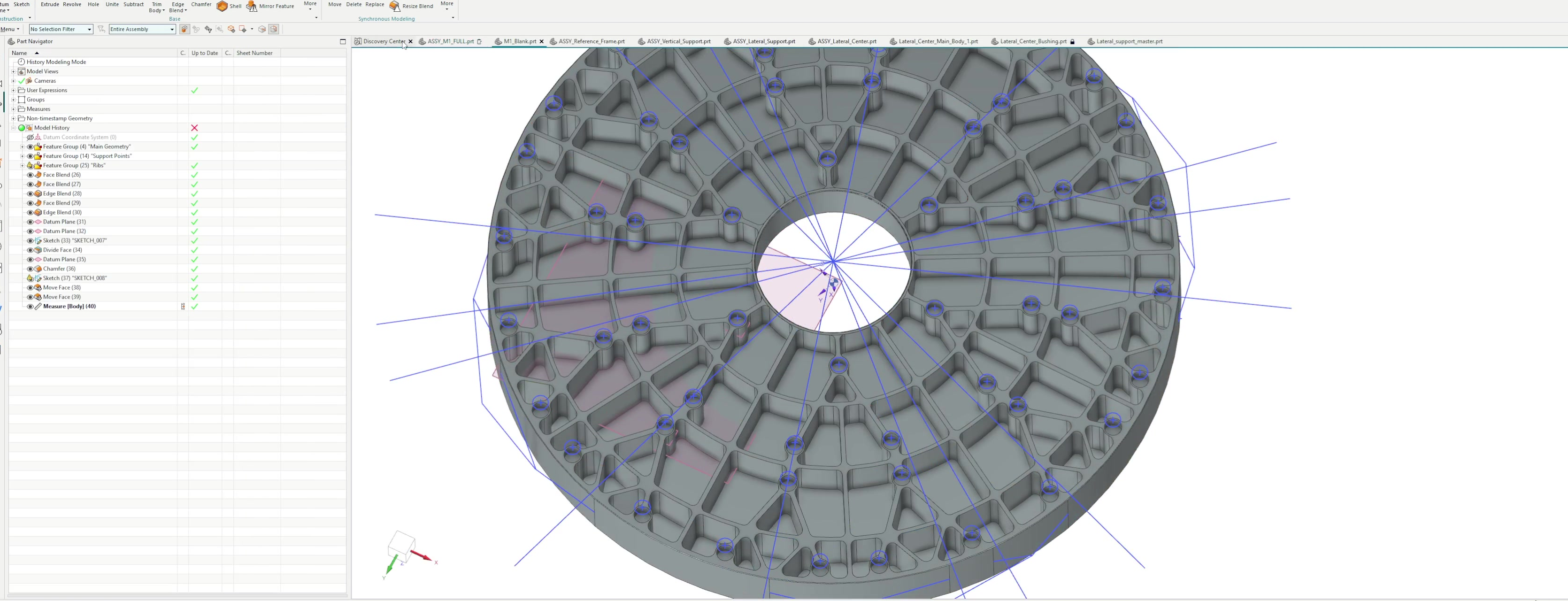
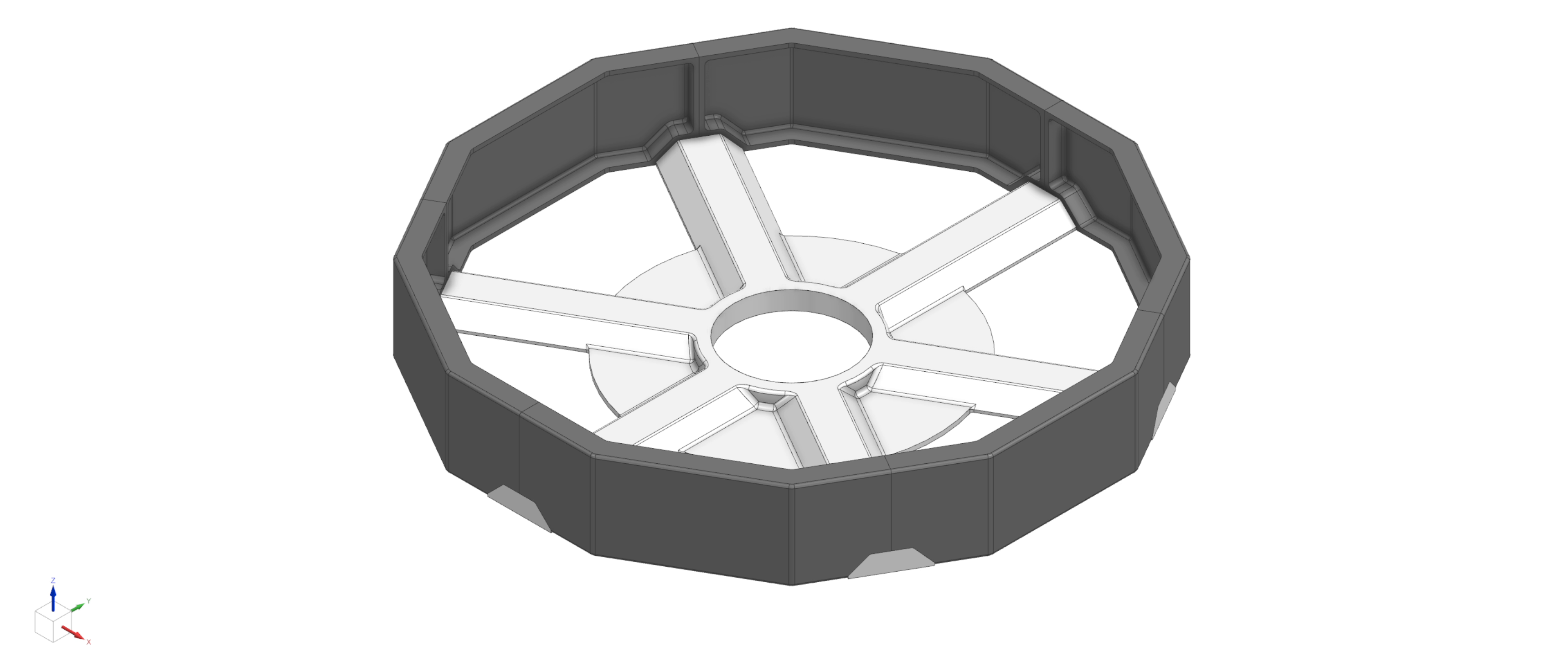
M1 Mirror Blank — Design Overview
Optical Prescription
| Surface | Near-parabolic (k = −0.9886) |
| Radius of curvature | 2893.6 mm ± 3 mm |
| Clear aperture | 1202 mm |
| Material | ZERODUR Class 0 |
Option B Geometry
| Back face angle | 4.01° |
| Center thickness | 85 mm |
| Mass | 95.81 kg |
| Support bosses | 54 (30 mm Ø) |
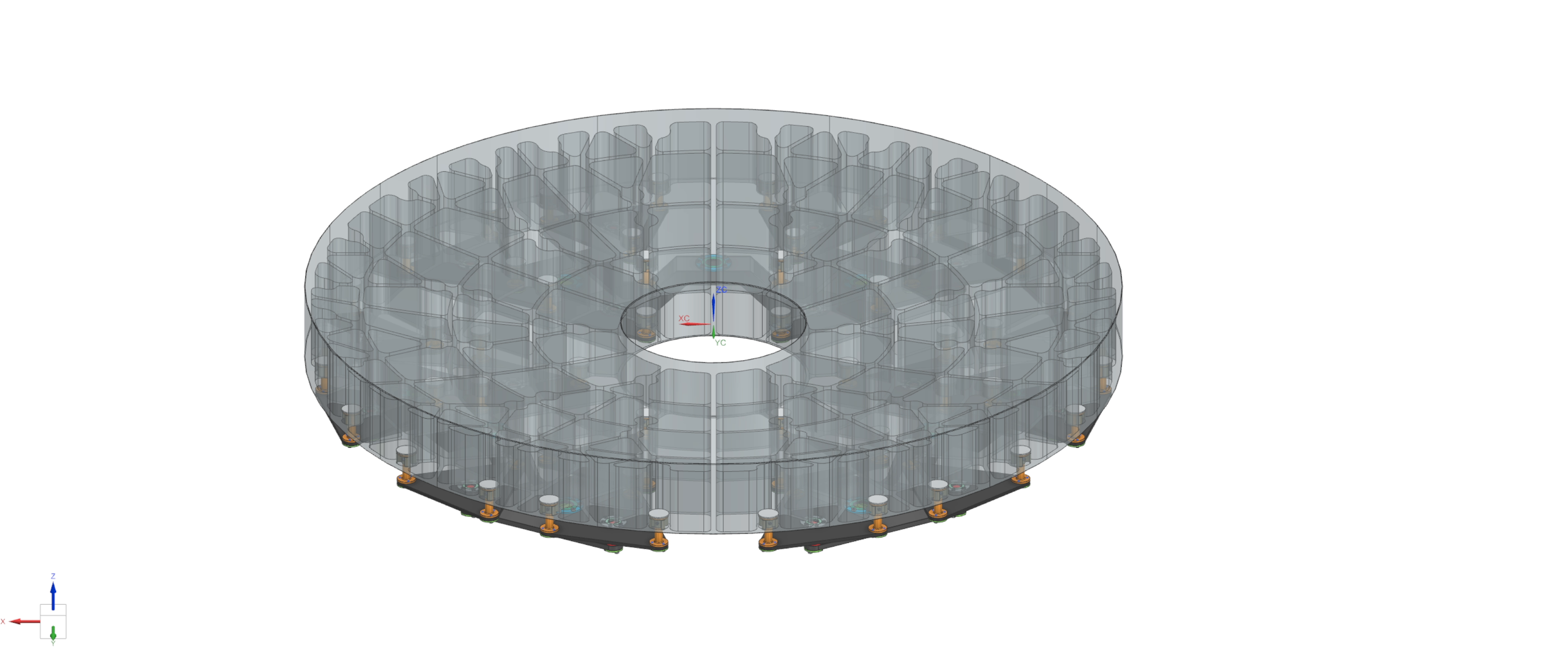
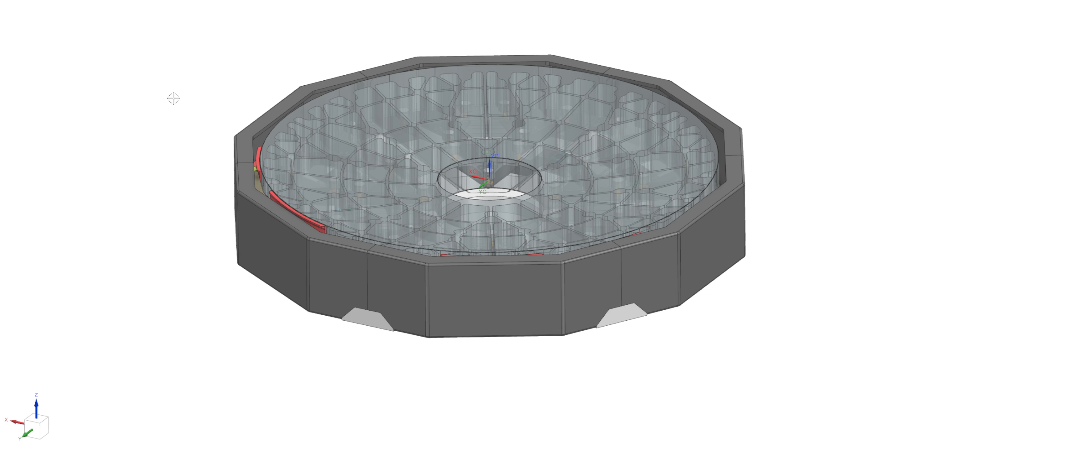
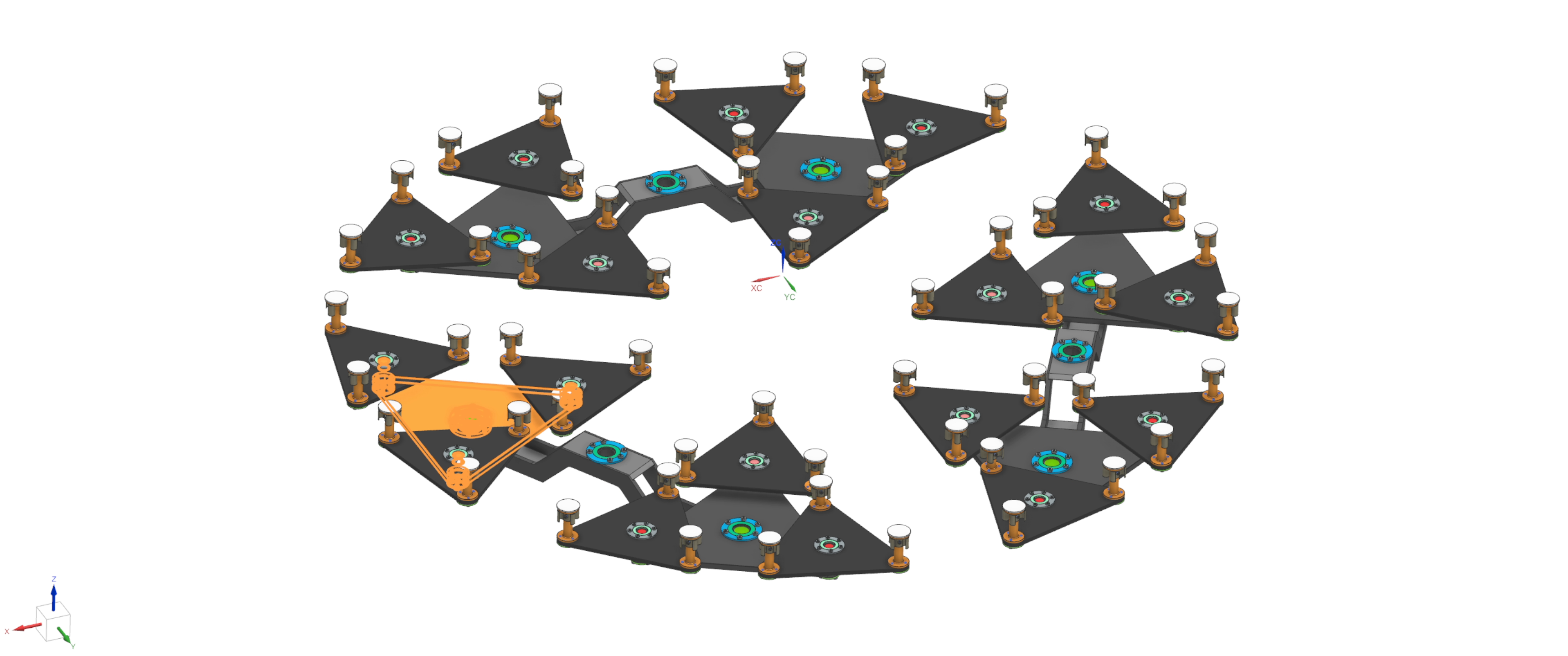
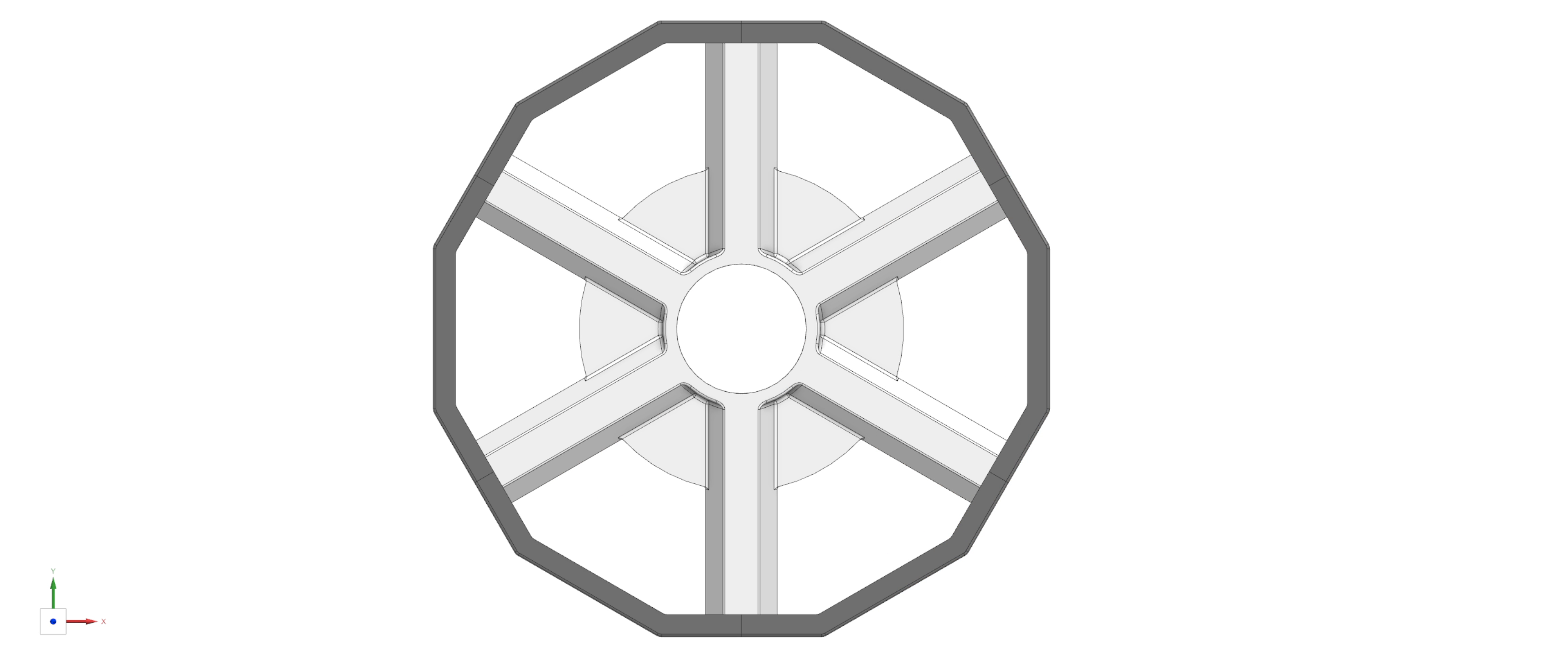
M1 Assembly
Support System Architecture
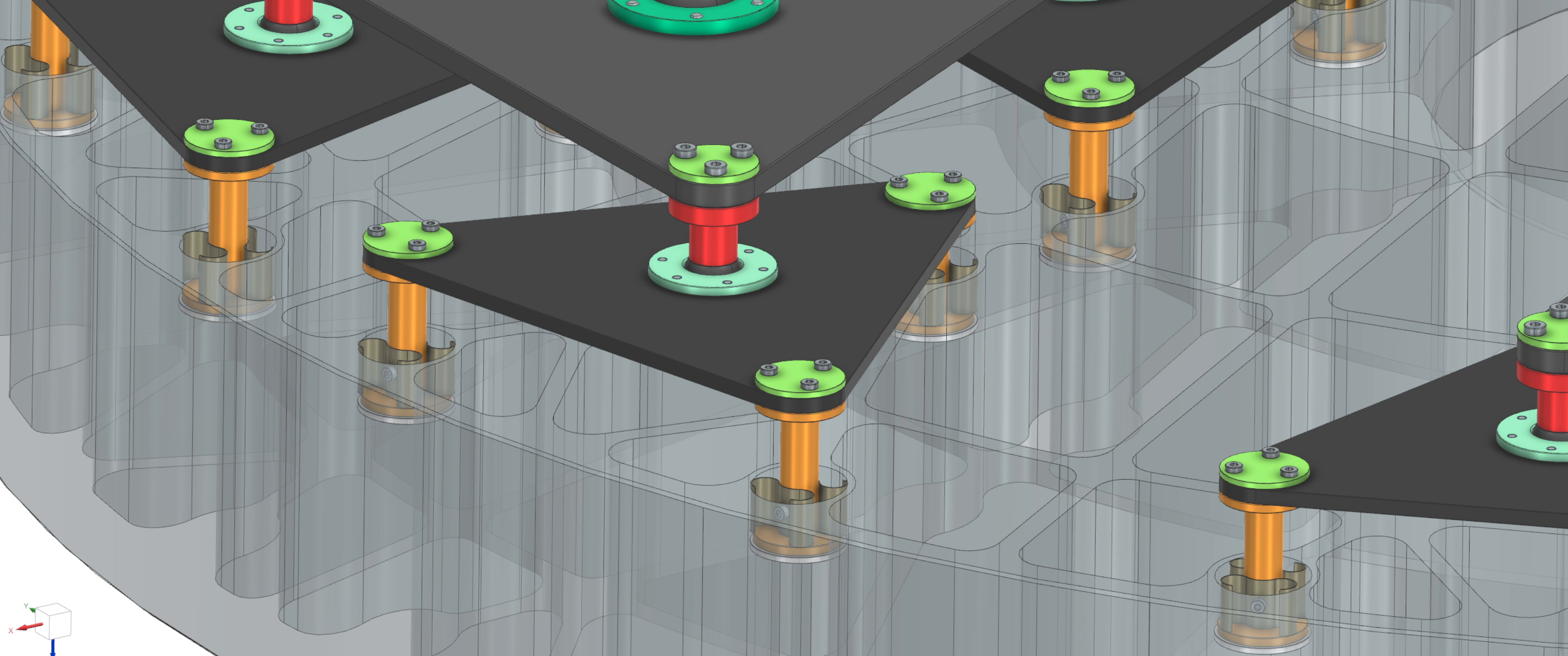
Vertical Support — 54-Point Whiffletree
- 3-stage hierarchy (18 contact points × 3)
- Carbon fiber plates for thermal isolation
- RDOF joints: 150 Nm·m stiffness (negligible WFE impact)
- Spherical joints for self-alignment
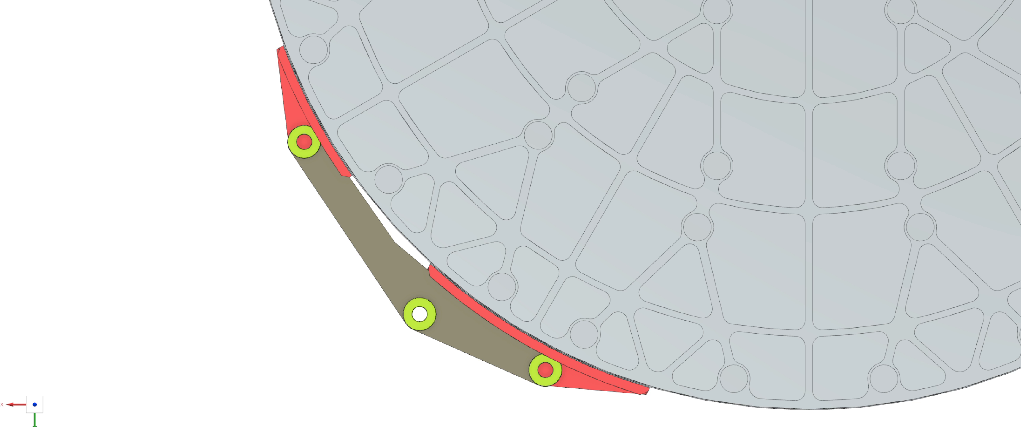
Lateral Support — 3-Point System
- Roll restraint ±7.5°
- Low-friction sliding interface (Teflon-like)
- Minimizes parasitic frame distortion transfer
- Parameterized pivot positions (inner/outer/middle)
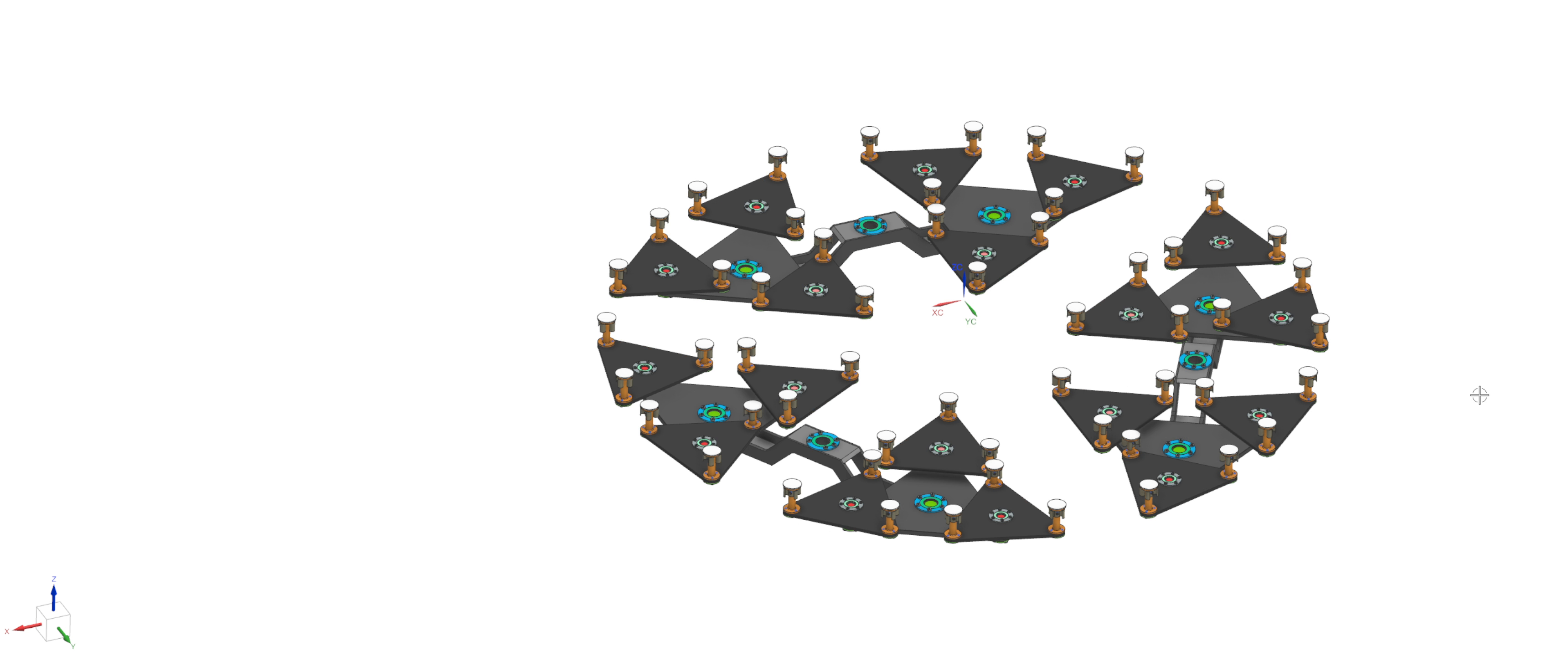
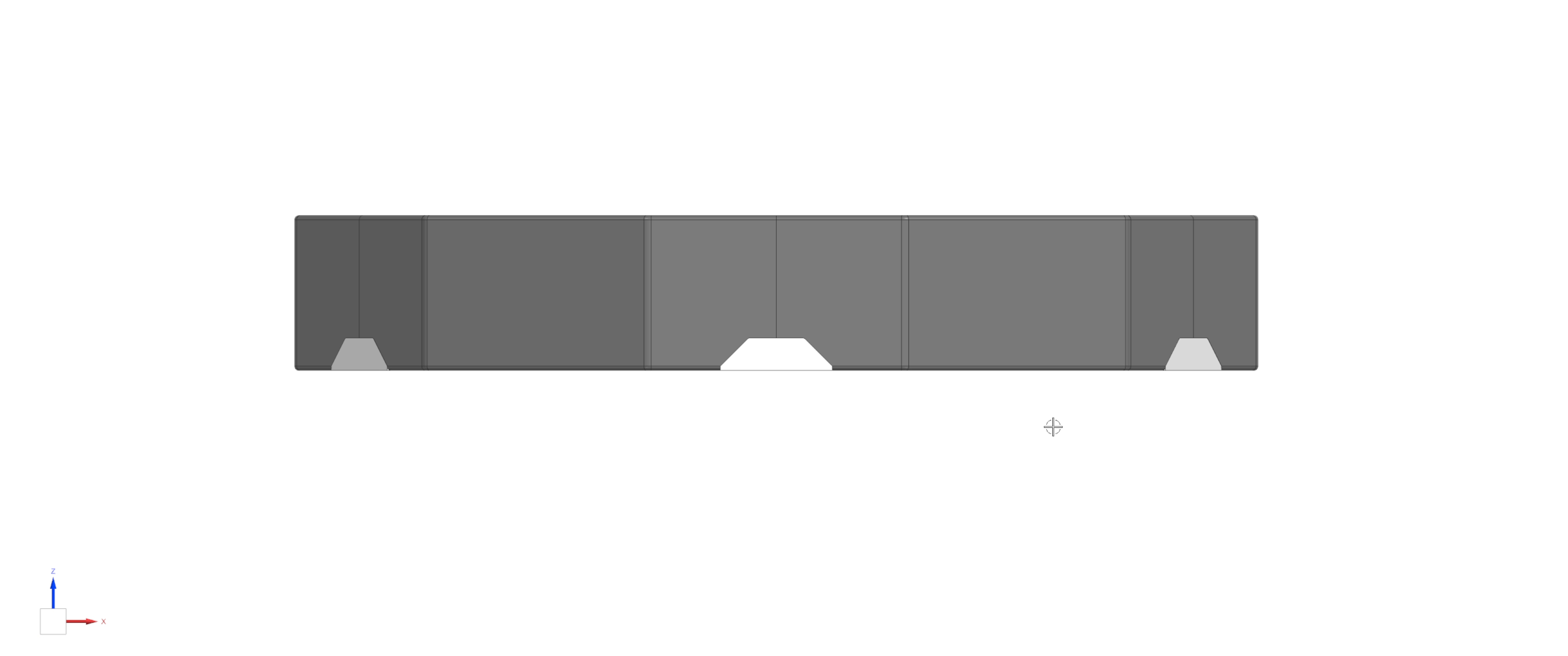
Support System — Detail Views


Reference Frame — Concept
Conceptual design provided by Optiques Fullum as a good-faith proposal to facilitate integration. Detailed design & manufacturing = StarSpec responsibility.
Optimization Campaign — Scale
| Campaign | FEA Trials | Algorithms | Focus |
|---|---|---|---|
| Adaptive Support | ~1,400 | GNN+TuRBO, TPE, NSGA-II | Support position optimization |
| Cost Reduction | ~900 | TPE, CMA-ES | Geometry simplification |
| Flat Back Exploration | 1,470 | TPE, SAT v3, L-BFGS | Manufacturing trade study |
✅ Design space thoroughly explored. Multiple algorithms converge to same solution.
Atomizer — Custom Optimization Framework
Evolution since PDR
- Transitioned from HEEDS MDO → Atomizer (fully custom)
- Full control over algorithm selection & tuning
- OPD-based Zernike extraction — accounts for lateral (X,Y) displacement, not just axial (Z)
- Complete traceability through version-controlled studies
Key Algorithms
- TPE — Bayesian optimization baseline
- GNN Surrogate — Graph Neural Network (~0.95 R² on Zernike coefficients)
- SAT v3 — Self-Aware TuRBO with adaptive exploration schedule
- L-BFGS — Gradient-based polish for final refinement
Cost Reduction Campaign
Problem: Schott quote $625K vs. $523K budget → $102K gap to close
Strategy 1: Geometry Simplifications
| Modification | Impact | Verdict |
|---|---|---|
| Remove structural ribs | +92% WFE | ✗ Rejected |
| Support cone → 0° | +3.3% | ✓ Acceptable |
| Remove center mini ribs | −1.6% | ✓ Recommended |
| Center thickness 85→80 | +8.2% | ✗ Rejected |
Strategy 2: Flat Back Variant
- Eliminates taper machining entirely
- No jig required
- 1,470 FEA trials across 10 versions
- 49% improvement in MFG deformation
- Mass trade-off: +16 kg
✅ Campaign closed the cost gap. Option B: $525K (+0.4% of budget). Option C: $520K.
Key Finding — Structural Ribs Are Non-Negotiable
The sensitivity analysis revealed a critical design hierarchy:
| Rank | Parameter | Sensitivity |
|---|---|---|
| 1 | Structural Rib Topology | CRITICAL (67–92% degradation) |
| 2 | Center Thickness | CRITICAL (+106% MFG) |
| 3 | Pocket Radii | HIGH (requires re-optimization) |
| 4 | Center Mini Ribs | POSITIVE (7–9% improvement) |
| 5 | Support Cone Angle | Low-Moderate |
| 6 | RDOF Stiffness | Negligible (<0.2%) |
⚠️ The ribs provide stiffness against asymmetric gravity deflection. Removing them increases high-order aberrations (J4+) by 2.4×. This finding de-risked the design decision.
Selected Design — Option B (Conical V14)
| Factor | Option B (Selected) | Option C (Trade Study) |
|---|---|---|
| WFE 40° | 7.70 nm | 8.09 nm |
| WFE 60° | 17.69 nm | 18.81 nm |
| Mass | 95.81 kg ✓ | 102.38 kg |
| Quote | $525,000 | $520,000 |
| Risk | Lower (proven geometry) | Moderate (new variant) |
Recent Development — Refined Lateral Contact Model
Design decision (Jan 30, 2026): Changed lateral shoe-blank interface from silicone adhesive to low-friction sliding material (Teflon-like).
Why this change?
- Mirror independence — blank floats freely within lateral supports
- No parasitic transfer — frame distortions decoupled from mirror
- Conservative — worst-case for self-support; actual friction → better performance
| Metric | Previous | Refined | Δ |
|---|---|---|---|
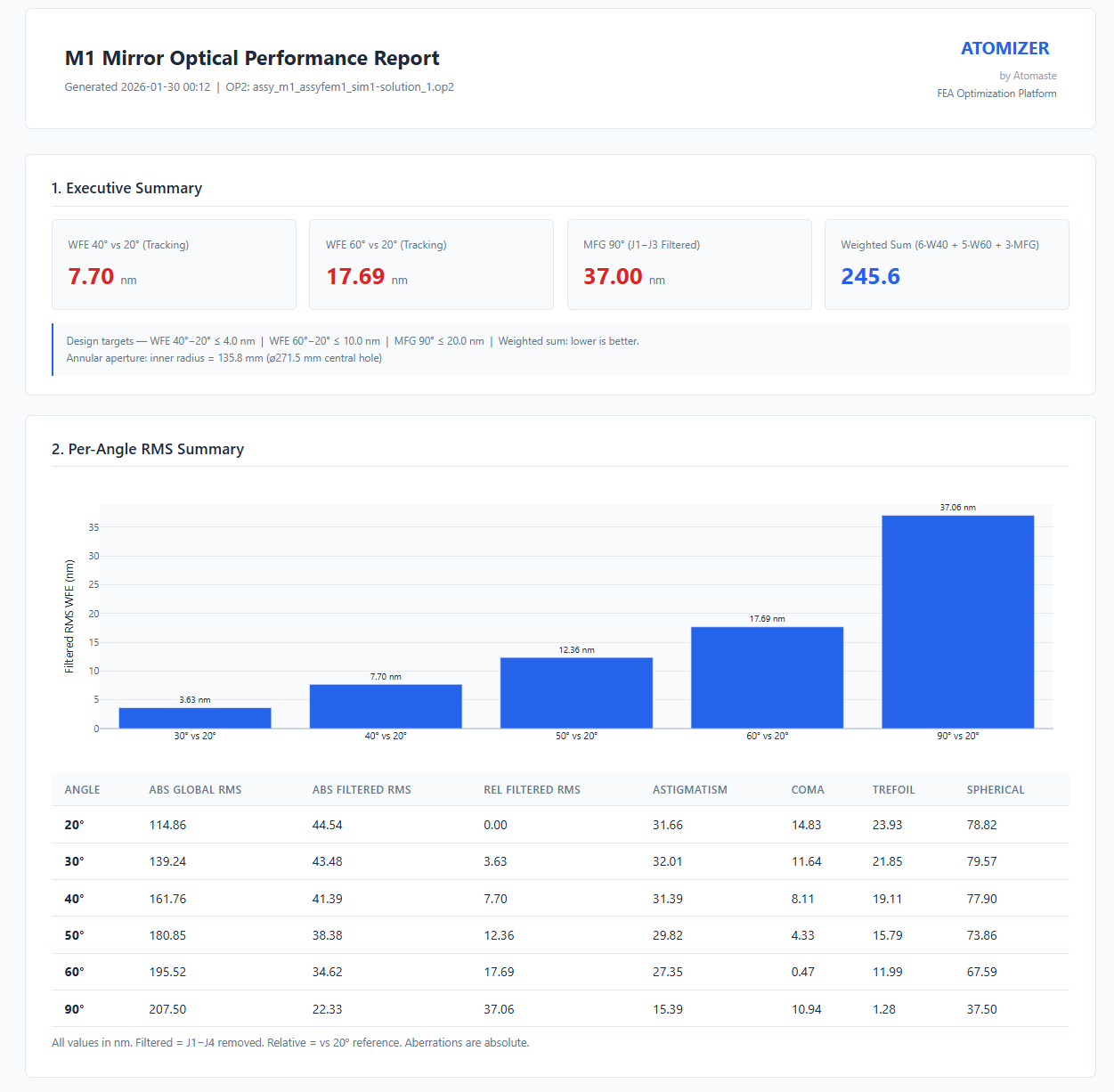
| WFE 40° | 6.12 nm | 7.70 nm | +26% |
| WFE 60° | 13.41 nm | 17.69 nm | +32% |
| MFG 90° | 27.01 nm | 37.06 nm | +37% |
✅ All values remain compliant with 22 nm requirement. Higher values = more physically accurate, not design degradation.
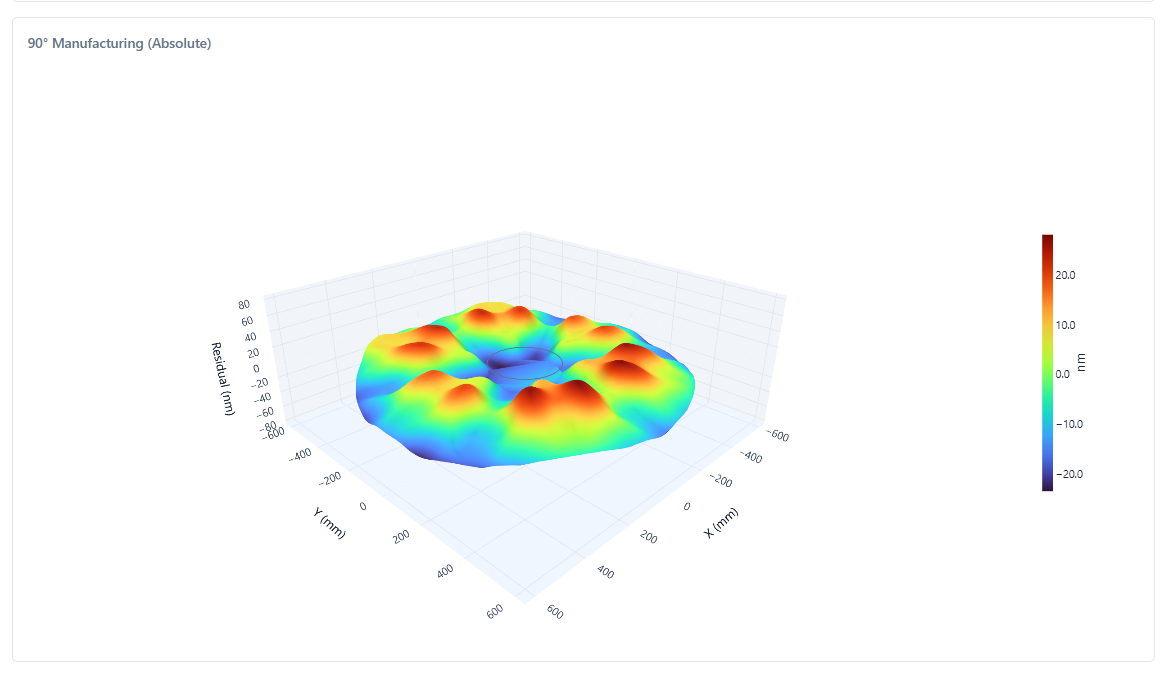
Optical Performance — WFE Surface Maps
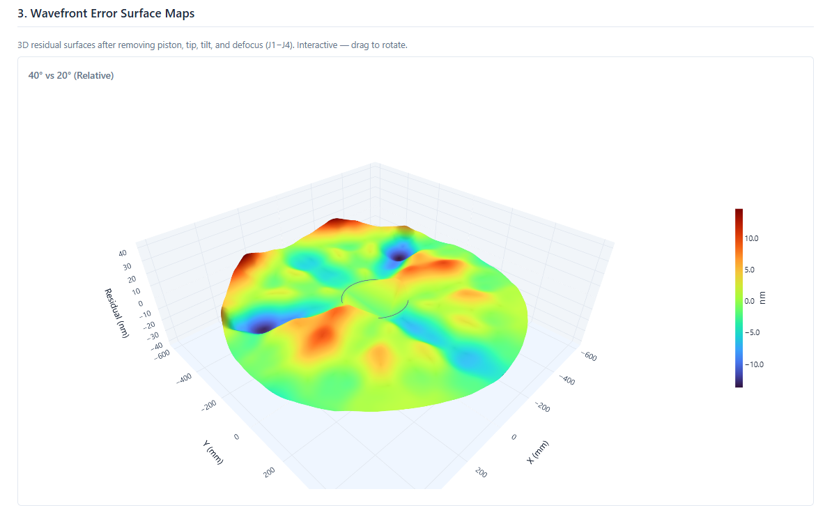
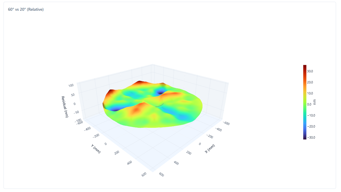
Refined contact model (Jan 30, 2026). J1–J4 removed (piston, tip, tilt, defocus corrected by active optics).
Manufacturing & Analysis Summary
Zernike Trajectory & PSD Analysis
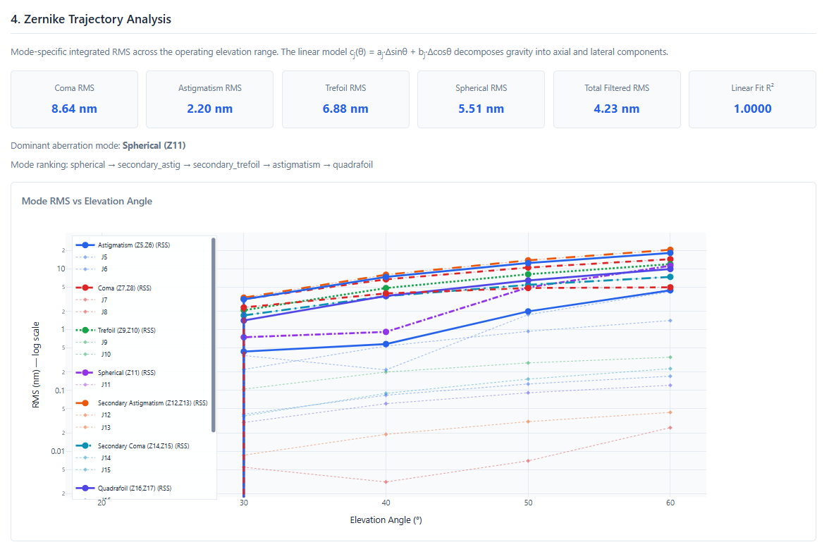
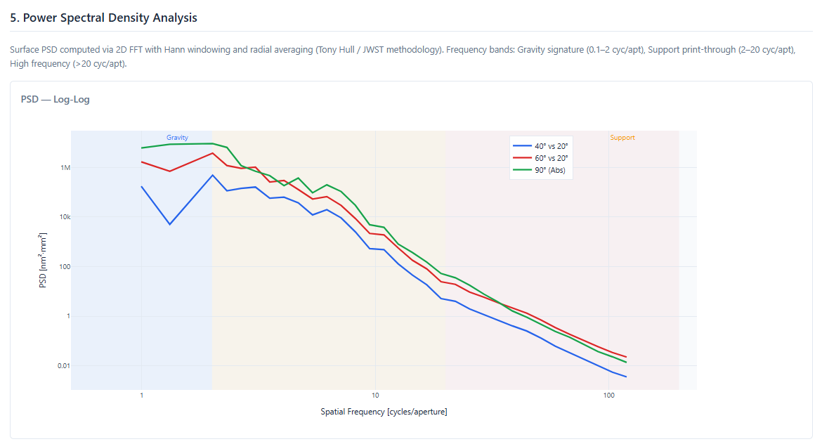
PSD analysis confirms support print-through dominates (71–85% of total WFE). Predictable and well-characterized behavior.
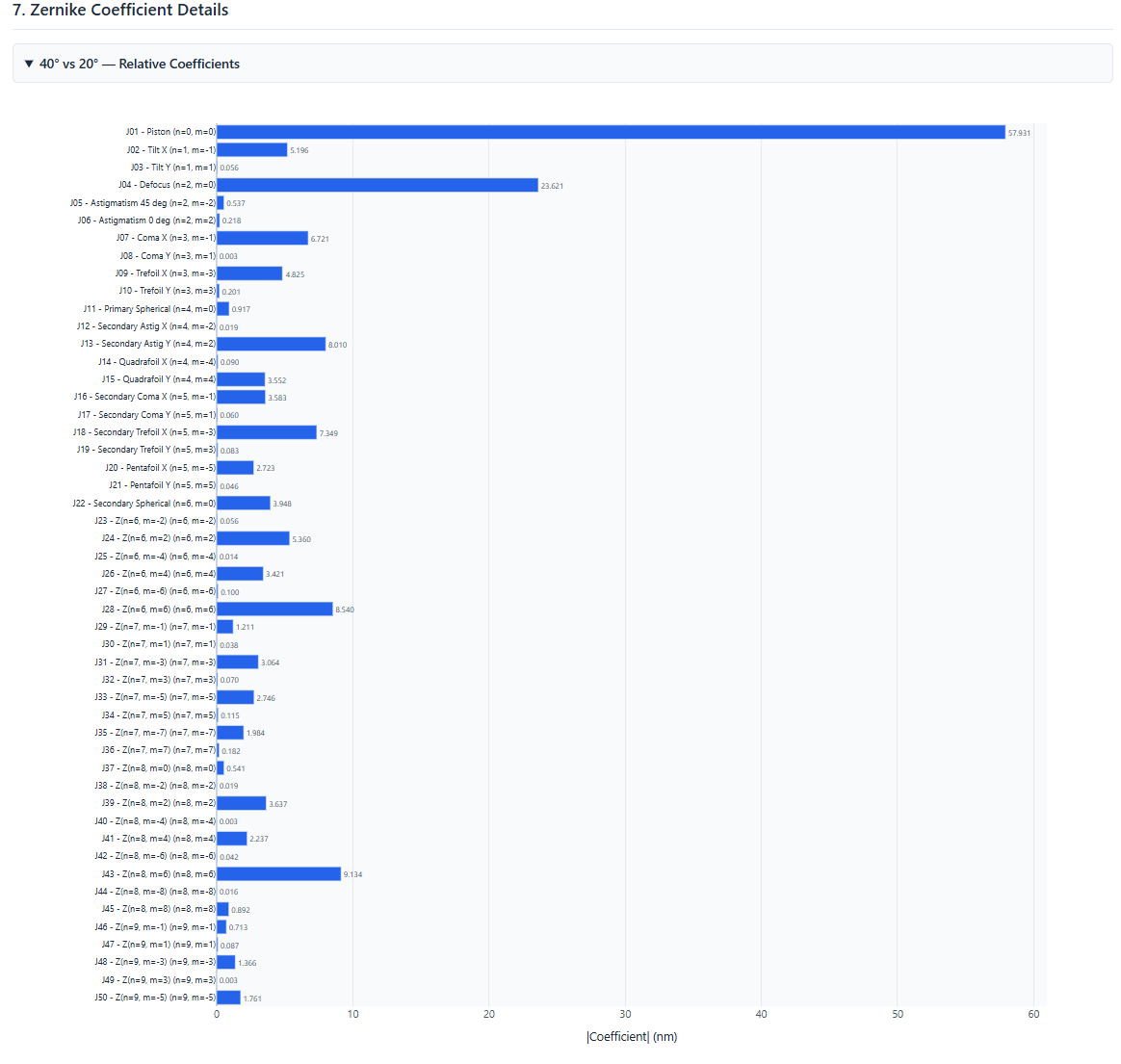
Zernike Coefficient Breakdown
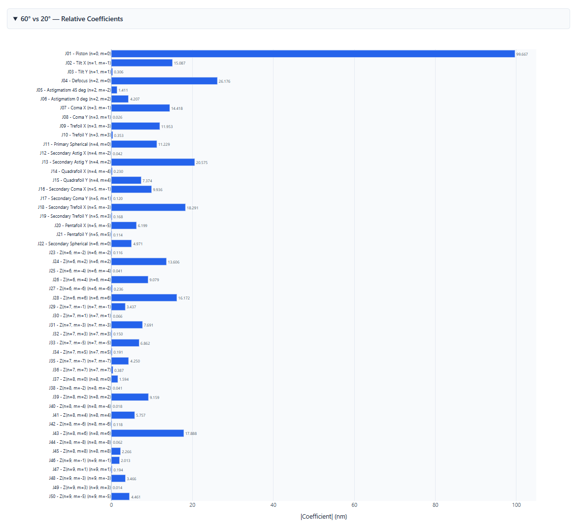
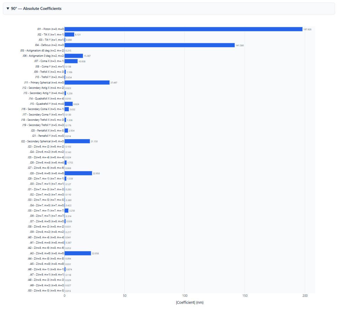
Modal Analysis — Natural Frequencies
First mode: 250.4 Hz — exceeds 150 Hz requirement by 67% margin.
| Mode | Freq (Hz) | Description |
|---|---|---|
| 1 | 250.4 | Trefoil bending (3-nodal dia.) |
| 2 | 259.3 | Astigmatic bending (2-nodal dia.) |
| 3 | 466.2 | Rocking/tilting |
| 4 | 668.8 | Higher-order bending |
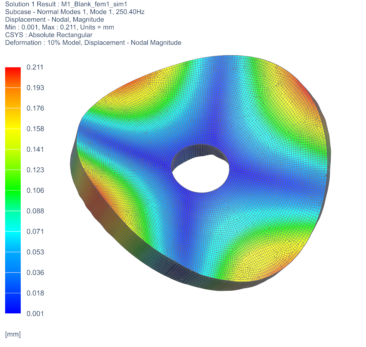
SOL 103 analysis with fixed BCs at all 54 whiffletree + 3 lateral support points. All 10 modes well above 150 Hz.
Boundary Condition Strategy
The Decoupling Approach
We deliberately decouple two problems that can be solved independently:
Step 1: Optimize blank for ideal fixed BCs → Complete (CDR)
Step 2: Engineer reference frame to approach ideal BCs → In progress (FDR)
Why this works
- Reduces complexity: 14 variables vs. 60+ (blank + frame coupled)
- Blank procurement & frame design proceed in parallel
- Clear success criteria: frame stiffness targets derived from WFE sensitivity
- Standard practice in large telescope projects (TMT, GMT, E-ELT)
The self-maintaining structure
The optimized blank is a self-maintaining structure — ribs aligned with gravity load paths, mass placed where stiffness is needed. Even with moderate support compliance, inherent structural efficiency limits WFE growth.
Reference Frame — Scope & Requirements
Scope Boundary
| Deliverable | Owner | Status |
|---|---|---|
| M1 Blank (Zerodur) | Optiques Fullum | CDR ✓ |
| Vertical Support (54-pt) | Optiques Fullum | CDR ✓ |
| Lateral Support (3-pt) | Optiques Fullum | CDR ✓ |
| Reference Frame | StarSpec | Concept proposed |
Frame Stiffness Targets
| Parameter | Requirement |
|---|---|
| Support point deflection | < 1 μm |
| First mode (frame + mirror) | > 150 Hz |
| Mass (frame only) | < 20 kg |
⚠️ CDR Open Item: ΔWFE vs. stiffness sweep not yet executed. Method is defined; execution is highest-priority post-CDR task.
Why It's Safe to Order the Blank Now
Evidence of Convergence
| Campaign | Improvement | Trials After Plateau |
|---|---|---|
| Flat Back V9 → V10 | +1.3% (worse) | 296 |
| Adaptive V13 → V14 | −5.9% (better) | 785 |
| Adaptive V14 → V15 | 0% (none) | 126 |
The Frame is a Solvable Problem
- Known physics — CFRP structural engineering, not research
- Conservative stiffness target (<1 μm) with margin
- Mitigation options exist if needed (local stiffening, shimming)
- Frame development is independent of blank design
🕐 Schedule driver: 18-week Schott lead time. Quote valid until March 4, 2026. Delaying for coupled optimization would extend program by months with uncertain benefit.
Risk Assessment
| Risk | L | I | Status |
|---|---|---|---|
| Design convergence | 1 | 3 | Closed |
| Cost exceeds budget | 2 | 2 | Reduced |
| Schott delivery delay | 2 | 3 | Open |
| Frame stiffness | 2 | 2 | New |
| Mass exceedance | 1 | 2 | Closed |
| Polishing difficulty | 1 | 3 | Reduced |
| Interface incompatibility | 2 | 2 | Open |
Trend Since PDR
| Category | PDR | CDR | |
|---|---|---|---|
| Technical | Medium | Low-Med | ↓ |
| Schedule | Medium | Medium | → |
| Cost | High | Medium | ↓ |
| Integration | Medium | Medium | → |
Technical and cost risks significantly improved since PDR. Risk posture supports procurement.
What's Done & What's Next
✅ Completed at CDR
- Mirror blank geometry — optimized & validated
- Support positions — optimized (14 variables)
- Cost reduction campaign — closed $102K gap
- Design selection — Option B confirmed
- Whiffletree architecture — defined
- Lateral support architecture — defined
- Refined contact model — conservative basis
- Schott quote received — $525K
🔜 Post-CDR Priorities
- Frame stiffness characterization (ΔWFE vs. K sweep)
- Reference frame preliminary design
- Whiffletree detailed design
- Lateral support detailed design
- ICD finalization with StarSpec
- Modal analysis (frame + mirror)
- STOP analysis (StarSpec scope)
Path to FDR — Timeline
Requirement Compliance Summary
| Category | Metric | Achieved | Requirement | Margin | Status |
|---|---|---|---|---|---|
| Optical | WFE 40° | 7.70 nm | 22 nm | 65% | ✓ |
| Optical | WFE 60° | 17.69 nm | 22 nm | 20% | ✓ |
| Optical | MFG 90° | 37.06 nm | — | Acceptable | ✓ |
| Mechanical | Mass | 95.81 kg | 103.5 kg | +7.4% | ✓ |
| Mechanical | Clear Aperture | 1202 mm | 1200 mm | — | ✓ |
| Cost | Blank Quote | $525K | $523K | +0.4% | ✓ |
| Dynamic | Mode 1 | 250.4 Hz | > 150 Hz | 67% | ✓ |
All requirements met with margin. Design is mature and validated.
Recommendation
Approve CDR & proceed with blank procurement
- Design maturity: 3,770+ FEA simulations, confirmed convergence
- Performance: WFE 20–65% margin (conservative contact model)
- Mass: 7.4% under allocation
- Cost: Within 0.4% of budget ($525K)
- Schedule critical: 18-week lead time — quote valid until March 4
Next investment: Reference frame characterization + detailed support design → FDR Q4 2026
The Investment Case — Continuing to FDR
What the next phase delivers
Frame Characterization
ΔWFE vs. stiffness curve — converts "reference frame risk" into a quantified, verifiable engineering requirement
Detailed Hardware Design
Whiffletree + lateral supports ready for fabrication. ICD locked with StarSpec.
Polished Mirror
Finished M1 primary mirror, verified against optical specs. Ready for integration.
Why continue now
- 3,770+ simulations have retired the major technical risk — blank design is settled
- The path from CDR → FDR is known engineering, not research
- Schott quote expires March 4 — delay means re-quoting at likely higher cost
- Parallel development maximizes schedule efficiency
Bottom line: The hard part is done. Proceeding now converts 4 months of computational investment into a validated, flight-ready mirror assembly.
Thank You
Questions & Discussion
Optiques Fullum & Atomaste Solution — January 2026
GigaBIT M1 Primary Mirror — Critical Design Review